
Home > SMT Equipment News
When a large number of PCBs have to be made, chances are that components won’t be manually soldered by hand. This is where professional assembly houses like Seeed will step in, to help fabricate both the bare boards and assemble all the parts onto the Printed Circuit Boards, or PCBs.
But have you ever wondered how your manufacturers are able to stick that massive number of tiny components onto your PCBs? I have, but that was until I had to plow through paragraphs of technical jargon online about the machinery that gets the job done. While there’ s nothing sexy about PCBA manufacturing, understanding how the brains of all electronics are made definitely brings joy and a sense of accomplishment. Lots of thought goes into each stage of the assembly process in order to deliver a perfectly functioning board. And with the electronics getting more and more advanced, machinery used to manufacture PCBs are ever-improving and more exciting than ever.
In this blog post, we shall explore what goes behind the scenes in PCB assembly!
In PCB assembly, there are 4 main stages of SMT, or Surface Mount Technology assembly using the reflow method, which are paste application, automated component placement, soldering, and inspection (plus testing, if requested). The basic equipment required for PCB assembly includes:
The first step in PCB assembly is the application of solder paste onto the board. Solder paste is a gray-colored goo made from a mixture of tiny particles of metal alloys; usually of tin, lead and silver. Think of it as a glue that will hold your completed board together. Without it, components wouldn’t stick to your bare board.
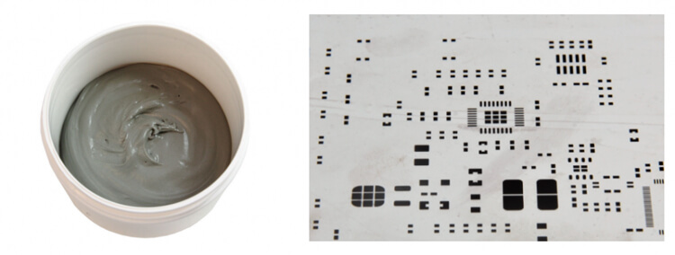 Solder paste (left), PCB stencil laser-cut holes (right)
Before the paste is applied, a PCB stencil is placed over the board. A PCB stencil is a stainless-steel sheet that has small laser-cut holes that allow solder paste to be applied only to the areas of the board where the components contacts will eventually sit on the finished PCB, i.e. the SMD pads.
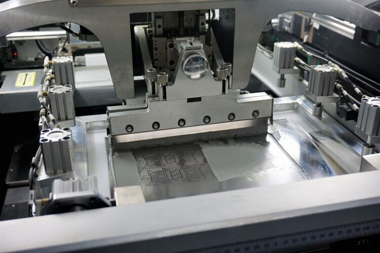
The solder paste printing machine in action
During the application of solder paste, the PCB stencil and the PCB are locked into place in the automated paste printer. A squeegee then applies lead-free solder paste on the pads in precise amounts. The machine then drags a blade across the stencil, to spread and deposit the paste evenly in the desired areas. After the stencil is removed, the solder paste will be exactly where we want it to be (hopefully).
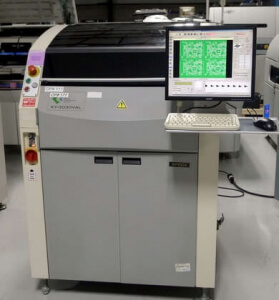
A Solder Paste Inspection machine
Numerous industry studies have pointed out that up to 70% of SMD soldering issues are traced back to improper or substandard solder paste printing. Hence, the next step is to check if the solder paste is printed properly onto the board. While employing good solder paste printing methods are often enough for PCBs in low volumes, SPI should be considered when churning out higher volumes of PCB to avoid high rework costs.
The SPI machine utilizes cameras capable of capturing 3D images, to evaluate the quality of the solder paste through factors such as solder volume, alignment, and height. The machine then rapidly identifies unsuitable solder volumes or imperfect alignment, allowing for manufacturers to quickly come down on bad solder paste printings and rectify the problem. When used together with Automated Optical Inspection (more on this later..), this enables manufacturers to effectively monitor and control the solder printing process, and therefore cut down on costs from rework and enable more efficient production of high-quality PCBs.
A glue dispensing machine
(source: Fritsch)
Prior to component placement, the glue dispensing machine applies dots of glue onto the PCB where the body of the components will sit, to hold them in place until the leads and contacts are soldered. This is important for wave soldering where the force of the solder wave may dislodge larger components, or for double-sided wave or reflow soldering to stop components from dropping off.
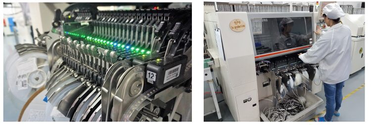
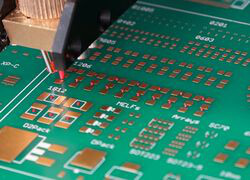
The pick-and-place machine is probably the most mesmerizing machine in the whole assembly line. As its name suggests, the pick-and-place machine picks up components and places them onto a bare board. Traditionally, this stage of the PCB assembly process is done by hand, where a human would painstakingly pick and place components using a pair of tweezers. But fortunately, PCB manufacturers nowadays have this step automated using the pick and place machine, as machines are more accurate than humans and can work around the clock.
Pick-and-place machines suction up SMT components and place them accurately at their pre-programmed positions on top of the solder paste. They are thrown down at lightning speeds, with machines easily achieving speeds of 30,000 components per hour. As the machine places components in an organized but almost frantic manner, watching pick and place machines doing their job is certainly the most amusing to watch!
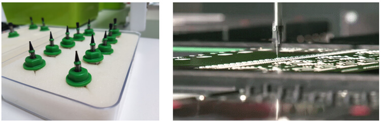 The little suction cups used to pick up components (left), and the automatic arm rapidly throwing parts down (right)
Also, we weren’t exaggerating about the tininess of SMD components.
Here’s a closeup of the opening where we feed components into the pick-and-place machine. Now, can you see where the SMD components are in this picture?
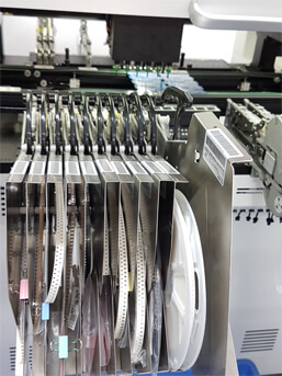
A little closer…
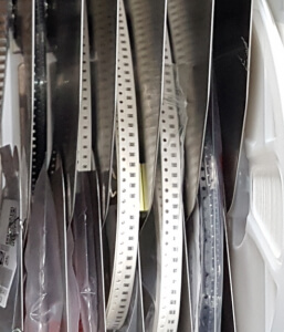
THERE THEY ARE.
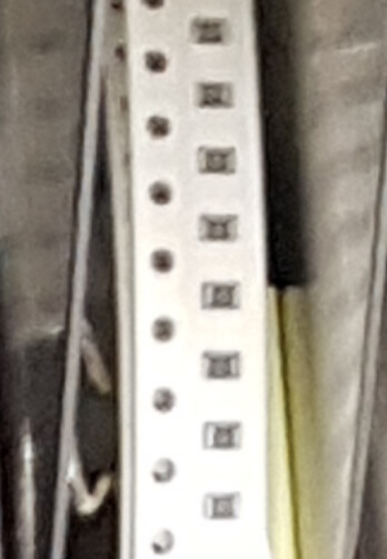
Shown in the picture are small surface-mount resistors. In fact, there exists SMD components that are much smaller than this one. So, boy are we thankful for pick-and-place machines!
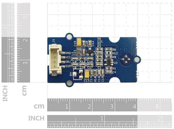
Tiny SMD resistors on the Grove Infrared Temperature sensor
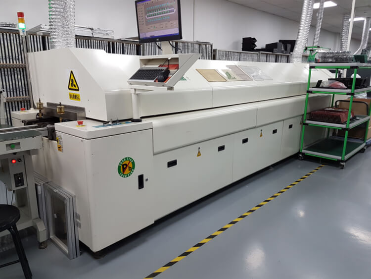
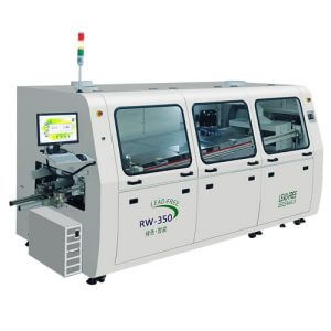
A Reflow Soldering Machine
Reflow soldering is the most widely used soldering technique for PCB assembly. Once the board is fully populated with components, the assembly is moved along a conveyor, through a long, giant oven called the reflow soldering machine. The PCB boards travel through various zones at carefully controlled temperatures, so that the solder paste melts and hardens steadily to form strong electrical connections between the components and their respective pads.
Wave soldering machines got their name from the fact that PCBs have to pass over a wave of molten solder in order to solder the components. At the start of the wave soldering process, a so-called flux layer is applied to clean all the component contacts and pads to ensure that solder can adhere properly. After flux application, the board is preheated to prevent thermal shock. Finally, a solder wave is set up within a tank of molten solder, and the PCBs are passed over such that the underside of the boards make contact with the solder wave, forming a connection between the components’ leads or contacts with their respective holes and pads.
However, wave soldering is less widely used for PCB assembly nowadays compared to reflow soldering, as the latter is much more effective in soldering the fine features being used nowadays on boards with surface mount components. As a result, wave soldering, and more recently, selective wave soldering methods are used to assemble through-hole components.
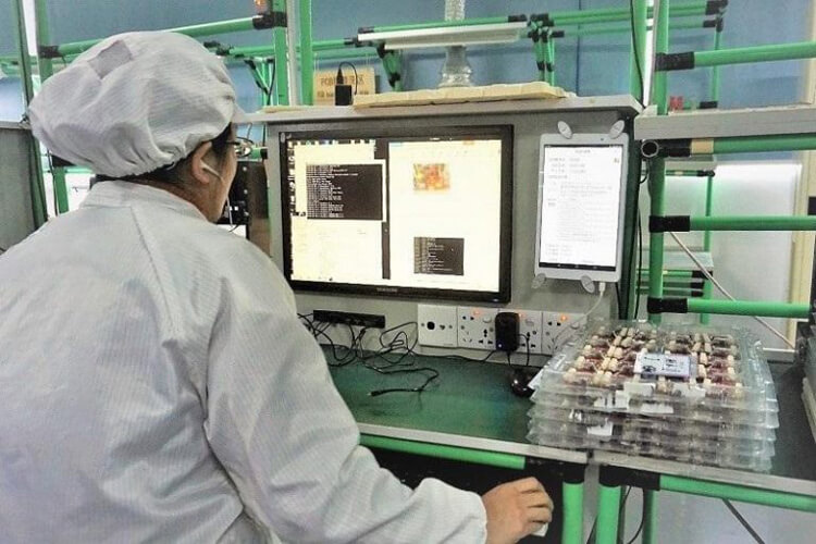
Now that the boards are fully assembled, it’s on to inspection and testing. With the increase in complexity of PCB boards, automatic optical inspection is more important than ever. While you can still try to squint and spot mistakes with your naked eyes, manual inspection is simply not effective for mass production, as operators soon become fatigued and mistakes become easily overlooked. Testing PCBAs is a crucial step in PCBA manufacturing in order to avoid costly re-manufacturing fees and wastage of materials. AOI systems are employed to detect problems early in the production process and to allow processes to be modified or individual boards to be rectified.
Using optical methods to detect defects, AOI systems can perform checks previously done by humans, but with far more speed and accuracy. The AOI machine uses high definition cameras to capture the surface of the board and build up an image of it for analysis. This captured image is then compared with images of a correct reference board, to identify a variety of defects from incorrect and missing components to shorts and scratches.
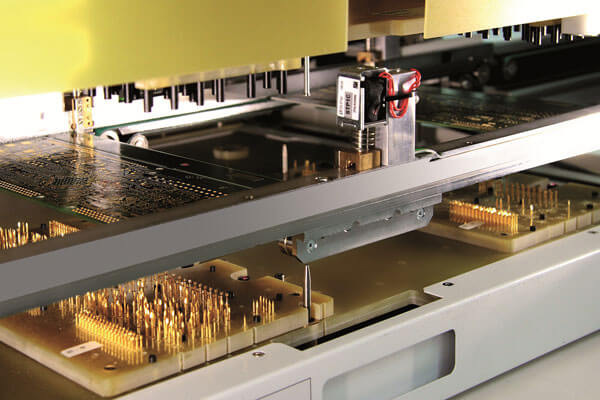
In-circuit testing is carried out using the “bed of nails” fixture
(Source: Spea)
Performed using a bed of nails fixture, the in-circuit testing (ICT) stage is one of the most widely recognized ways to quickly test the functionality of populated PCB boards. Named after the real-world bed of nails due to the test bed’s uncanny resemblance to the torture device, the test fixture consists of an array of spring-loaded pogo pins arranged such that each pin makes contact with one node in the circuitry of the PCB. Each completed board is placed on top of these pins and pressed down, and contact can be made quickly with hundreds of test points on the PCB. Through these test points, the fixture can rapidly transmit test signals in and out of the PCBs, to evaluate its performance and detect breaks in electrical continuity or shorts.
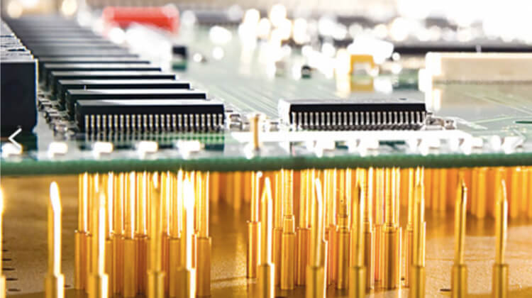
Ouch
PCBAs that have been tested on the bed of nails may show evidence of this from the small dimples seen on the soldered connections, due to the sharp tips of the pins. So don’t be alarmed when your PCBAs arrive with little dents! It’s a cause for celebration, because it’s a sign that your manufacturer has properly conducted tests to ensure that your boards are good to go.
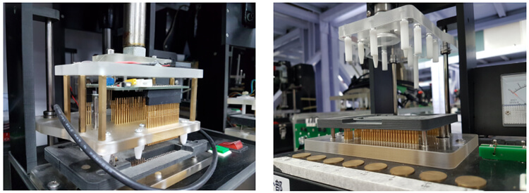 Seeed’s ICT equipment
Functional Validation Testing (FVT) is the final step that provides the go or no-go decision on completed PCBs before they are shipped. By this time, we are no longer just testing for physical defects like solder bridges or tombstones. Instead, software is loaded and we are testing whether the board will work as it should when it’s used in whatever application our customers have in mind for them.
FVT simulates the final operational environment that the PCB will be used in, typically by interfacing the PCB via its connector or a test point. Functional tests differ from product to product, as each PCB tested is unique. The most common form of functional test are “hot mock-ups”, which is a setup configured to simulate the end-product where the PCB will be used in. But regardless of how the FVT is customized, they share the common components of a system, the hardware, and the software.
If you’ve made it this far, we hope that you now have a better idea of how a PCB is assembled!
Keywords:
SMT Assembly line, PCB Assembly line, LED Production line, Automatic SMT Assembly line, Semi Automatic SMT Assembly line, JUKI SMT Assembly Line, Samsung SMT Assembly Line, Hanwha SMT Assembly Line, Panasonic SMT Assembly Line, FUJI SMT Assembly Line, Yamaha SMT Assembly Line.


Contact: Mr Tommy
Phone: +86 13691605420
Tel: +86 -755-85225569
Email: tommy@flason-smt.com
Add: 94#,Guangtian Road,Songgang Street,Bao an District Shenzhen China