
Home > SMT Assembly News
With more and more home assistants and voice interactive devices appearing in the consumer domain, microphones are being incorporated in more and more devices than ever before in increasingly more compact forms. This has encouraged the emergence of new technologies like the MEMS (microelectrical- mechanical systems) technology and more recently, case mounted versions for improved performance, but this comes at the expense of ruggedness and structural integrity. Subsequently, it is no surprise that these smaller, more fragile packages demand extra care and proactive planning during the production stage.
Seeed is very aware of the risks involved with MEMS microphones and the potential consequences of poor preparation. As experience with the ReSpeaker line of voice assistants and mic arrays has proven, proactive planning is vital to high yields and long-term reliability. In this article, we share some of our experiences with these parts and provide some advice to prevent damaging these delicate devices.
MEMS microphones, also known as a microphone chip, is a miniature SMT acoustic device that picks up sound waves. It typically consists of two parts situated side by side; the ASIC chip and the MEMS acoustic sensor mounted on a PCB board, which is then enclosed within a metal or plastic casing. Sound waves must enter the enclosure to reach the acoustic sensor somehow, so inevitably a physical hole is needed somewhere on the package. This hole or sound port can be located on the top of the package on the enclosure, or on the bottom. If it is located on the bottom, a hole needs to be drilled into the main PCB board as well.
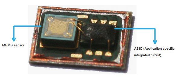 Bottom-port MEMS sensor with the casing removed. The rigid plate of the MEMS sensor can be seen on the left.
The MEMS sensor is essentially a capacitor with two plates; a fixed rigid plate perforated with holes, and a fine membrane electrode, or diaphragm. When sound waves impact the membrane and cause it to oscillate, the change in spacing between the plates induces a charge which is converted into a digital or analog signal.
Two air chambers are involved in assisting the oscillations and have an impact on sound quality. Sound waves enter through the sound port into a front chamber and then cause the membrane to oscillate. Air pressure escapes through the back chamber that allows the membrane to return to its original position.
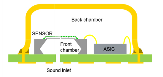
Side cross-section view of a bottom port MEMS microphone
Bottom-port MEMS microphones such as the MP23ABS1 by ST have the inlet located directly below the acoustic sensor which maximizes the size of the back chamber. A larger volume in the back chamber allows the membrane to move more freely and therefore increases the signal to noise ratio (SNR) and improves low-frequency response. Likewise, a smaller front chamber improves high-frequency response by removing the Helmholtz resonance to a higher frequency. This configuration provides optimal performance but comes with a downside.
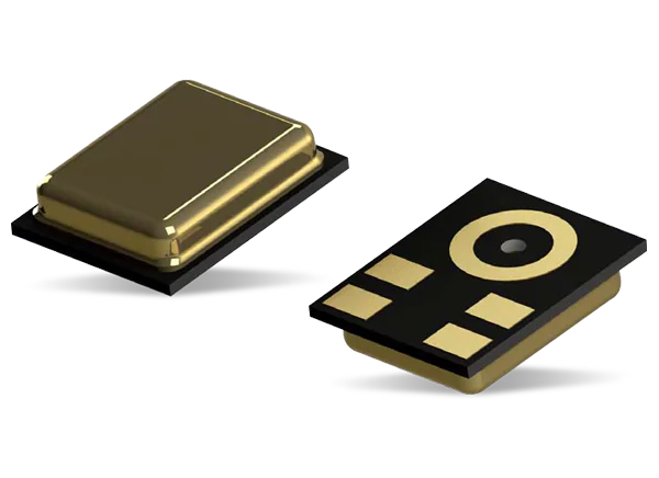
Top and bottom sides of the MP23ABS1 MEMS microphone by ST
For these types of microphones, the hole is located on the same side as the solder pads, so care has be taken to prevent solder or flux leaking into the opening during soldering. Therefore, it goes without saying that wave soldering is not recommended.
With a typical reflow soldering procedure using an appropriately designed stencil, solder should not find its way into the inlet. Bottom-port MEMS mics can be identified by the characteristic ring-shaped ground pad encircling the sound port. The corresponding opening in the stencil should be designed as follows:
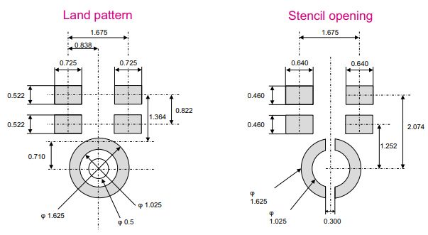 Land pattern and stencil opening for the bottom-port MP23ABS1 microphone as recommended by the manufacturer.
It is important not to open the entire area up, otherwise paste will be applied to the port directly and a no-clean solder paste should be used to prevent expelled flux from leaking into the hole. If applying the paste by hand, extra care should be taken to align the pads accurately and when lifting the stencil from the board to avoid smudging the solder paste.
When designing the gasket, the PCB thickness has to be taken into account for bottom-port mics. The thicker the PCB, the larger the front chamber becomes and the greater the effect on frequency response. Therefore, it may be worth considering flex PCBs for bottom-port MEMS mics as it will be easier to position the inlet flat with the enclosure and you can take advantage of the thinner substrate.
Traditional top-port MEMS mics are the same as bottom-port variants except the hole is placed above the sensor in the enclosure directly. This reverses the two chambers and produces a mic with inferior properties. Some models like the MP34DT01 have the hole located above the ASIC instead to protect the membrane from dust and more recent technologies make the most of both worlds by mounting the sensor and ASIC on the casing itself. These have the improved performance of bottom-port mics without the soldering complications.
For top-port mics, like the MP34DT01-M, the danger is present during the pick and place stage. The port is usually not located in the center of the component but with varying machine and packaging tolerances and the potential slip of the hand, there is the possibility of the pick and place nozzle going through the inlet and damaging the inside of the devices. Therefore, a designated safe pick area is often defined in the manufacturer’s datasheet. Satisfying this safe pick area can help reduce such incidences. Alternatively, specifically designed nozzles that pull on the four corners of the package rather than the center offer the best guarantee. If placing by hand, consider using tweezers instead.
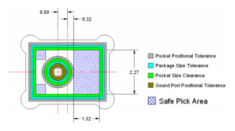
Recommended picking considerations for MP34DT01-M
By following the above guidelines, the dangers presented by the sound port can be averted. However, as Seeed’s production line engineers discovered, the boards were not out of the woods yet.
Seeed’s ReSpeaker Mic Array v1.0 has seven top-port MP34DT01-M microphones; one in the center and seven spaced equidistantly around the edge of a circular board. The ReSpeaker mic array was designed to be able to locate the position of the source, so the six outer mic units are spaced as far away from each other as possible. However, this meant they were situated in particularly precarious positions.
In early production runs, an unusually high proportion (around 10%) of mics in the four corner positions completely failed or had poor performance. Post reflow part substitution isolated the problem to the mics and since the failures were almost always located in these four areas, suspicion was directed to the design of the panel.
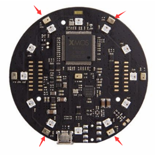
Location of the four defective mics
5mm away from each of these four mics were the four tabs that held the board in the panel. To free the board, a bending action is applied to break the tabs. Seeed’s engineers speculated that, despite having stamp holes lining the board edge and sufficient component to board edge spacing, the force may have been enough to damage the delicate mics.
Samples of the defective mics were returned to the supplier for professional analysis and the findings confirmed that the inner membranes of the mics were damaged by mechanical stress. Strain gauge analysis verified that the depaneling stage was indeed the most probable point of failure and the cause of the membranes’ rupture.
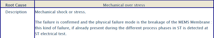
Component Damage Report
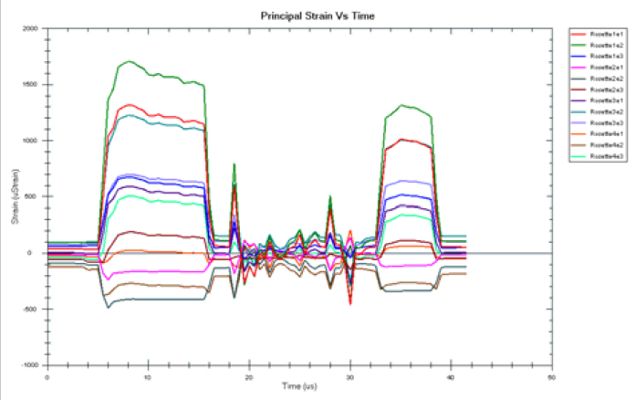 Strain gauge analysis
To resolve the issue, the panel was re-designed to simply move the tabs so that they were located in the middle of two mics, at least 15mm away from the tab, and the width of the tab was reduced. This effectively eliminated failures and increased the yield considerably.
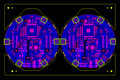
Relocating and reducing the width of the tabs did the trick. Mics highlighted in green.
Lessons were learned and the experience highlighted the mechanical fragility of the devices. In many consumer devices, it is not too uncommon to find the microphones near the edge of the device such as with a phone. This may mean the microphone is located near the edge of the PCB where it can be exerted to excessive mechanical stress both before and after it leaves the shop floor. Caution should be exercised when designing the panel according to the intended depaneling method.
MEMS microphones have relatively demanding design requirements that should be factored into the PCB and final product design as early as possible. Gasket design and top/bottom configuration may play a big role in determining the position of the mic in the device and may even influence the shape of the product enclosure. Then, it is important to ensure the assembler is aware of the necessary precautions to optimize yield.
Keywords:
SMT Assembly line, PCB Assembly line, LED Production line, Automatic SMT Assembly line, Semi Automatic SMT Assembly line, JUKI SMT Assembly Line, Samsung SMT Assembly Line, Hanwha SMT Assembly Line, Panasonic SMT Assembly Line, FUJI SMT Assembly Line, Yamaha SMT Assembly Line.


Contact: Mr Tommy
Phone: +86 13691605420
Tel: +86 -755-85225569
Email: tommy@flason-smt.com
Add: 94#,Guangtian Road,Songgang Street,Bao an District Shenzhen China